Stanley 358 Mitre Box Restoration
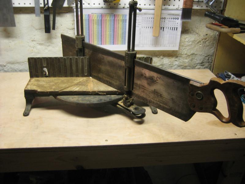
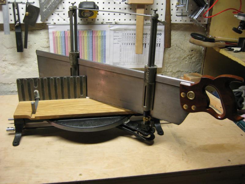
Here’s my Stanley 358 Mitre box in the condition that I purchased it for a whopping $35. I’ve seen a number of these on ebay, but the shipping is usually more than the item sells for. So when I saw this at a local used tool store, I snatched it up. For those who don’t want to read about the process of restoring, replacing, and rebuilding parts, here’s the before and after:
Like every used tool I’ve purchased in Oregon it had a good patina or what some call rust. The picture doesn’t show it, but most of the japanning had started to fall off as well.
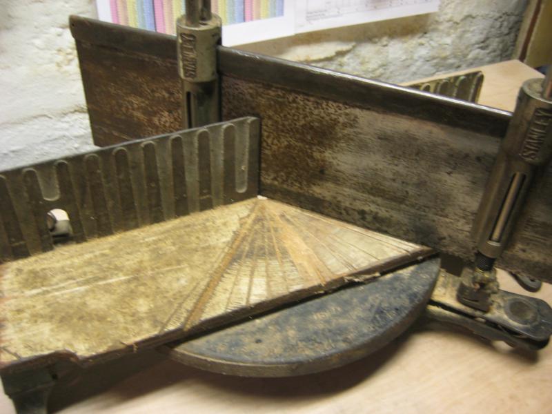 First, I start with stripping off all the old paint. For this I used paint stripper, which is my new least favorite task when restoring a tool. I thought about letting my electrolysis bath strip the japanning off but I wanted to keep the nameplate on the side in tact and it was attached with rivets that didn’t want to come out easily.
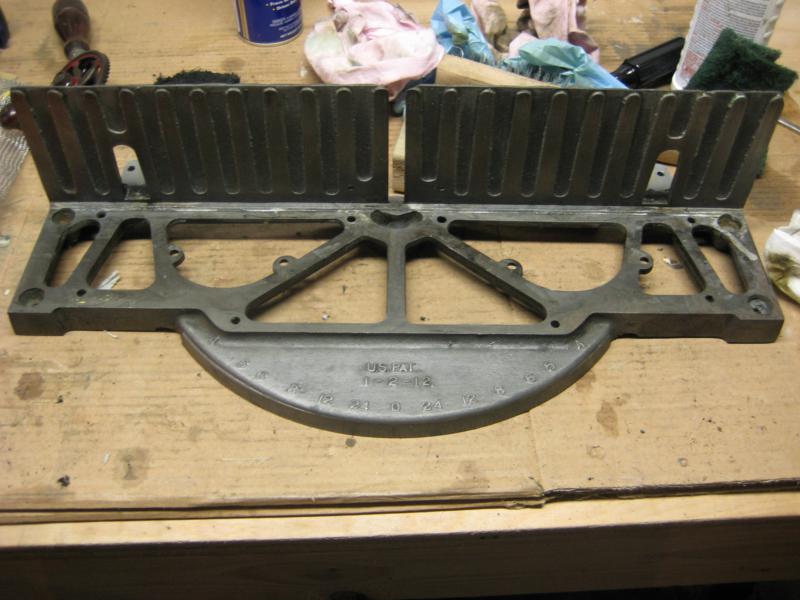 After all the paint was stripped I used a degreaser on all the parts. I then took them out to my “paint booth”. For the spray paint I used duplicolor engine enamel.
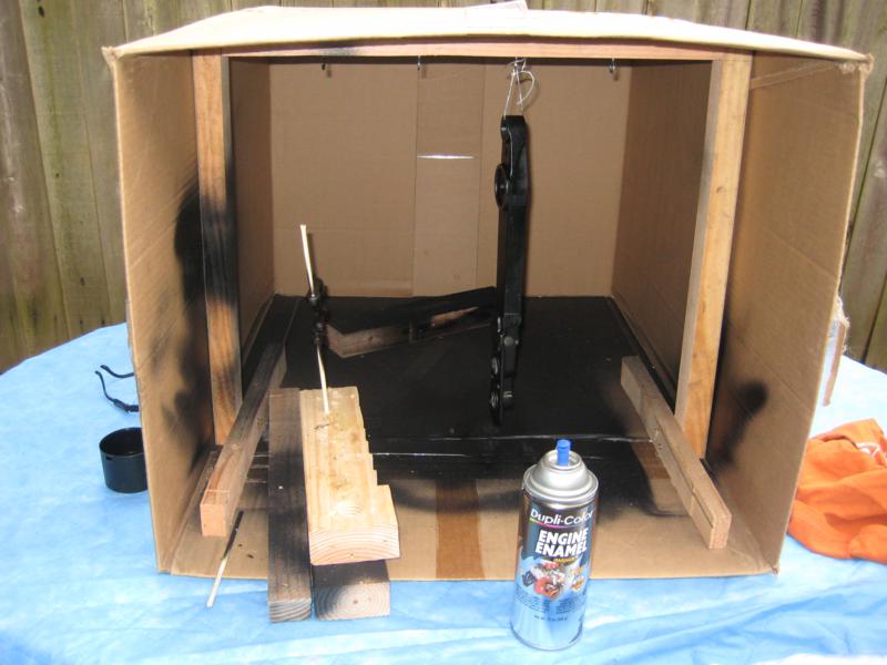 I’ve seen this recommended as a japanning replacement and I have to say it looks quite good.
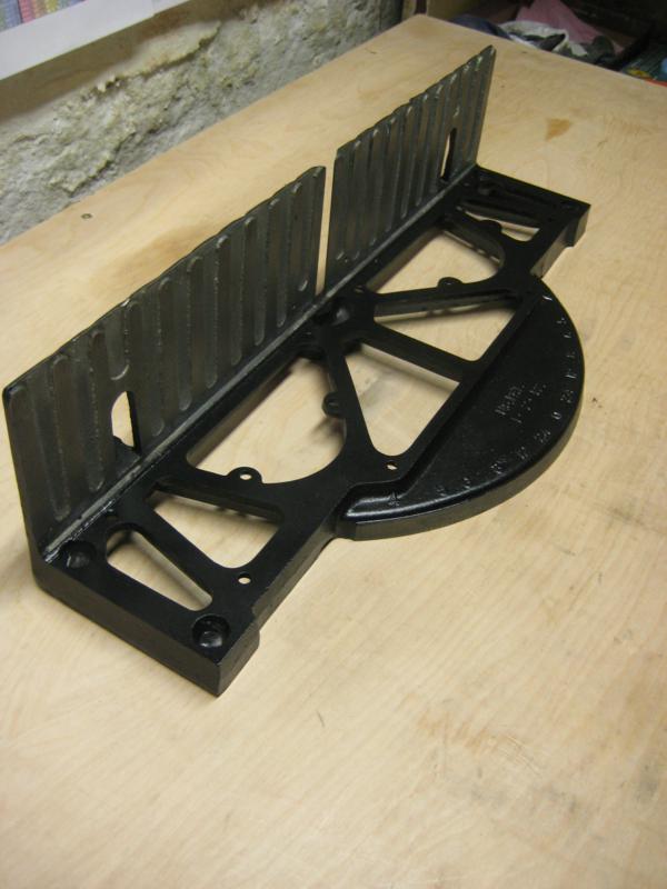 From what I can gather from looking at a few pictures of how the mitre box would have looked originally, the back face of the mitre box would have been painted with a silvery/aluminum paint. I played around with a few different spray paints, but nothing looked quite right. In the end, I decided to leave the back as bare metal with some BLO on the rough parts to darken them up to give a little more contrast with the machined pieces.
For the small parts I soaked them in evaporust and polished some with abrasive pads. To clean up the saw plate I first used a razor blade to remove the heavy rust, then sanded it using mineral spirits, a sanding block and more abrasive pads in varying grits. For a more detailed explanation of the process see the Saw Blog entry on cleaning up a saw plate.
Saw Handle
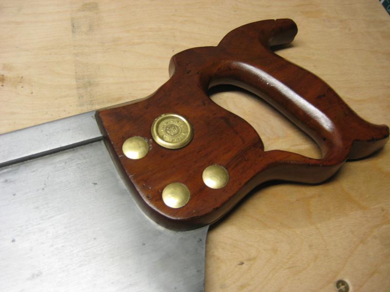
To clean up the saw handle I first sanded off all the old finish with some 120 grit sand paper. I then sanded with 220 and then abrasive pads. For a finish, I did two coats of boiled linseed oil(BLO) and french polished with amber shellac. For applying the shellac I used a technique outlined by Sauer & Steiner who make beautiful infill planes.
The majority of parts were still there except for some pretty common missing/worn parts:
- frame board – the sacrificial piece that goes under whatever you’re cutting
- cross bar – provides support for the two guide posts
- stock guides – holds the work piece
- length stop rods
- length stop coupler
- length stop stand or “tree”
For more information on these pieces go to ToolTrip and click on “Stanley Tools” and then go to the mitre box section.
Frame Board
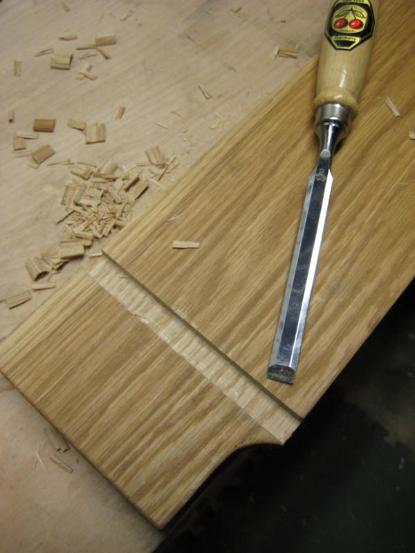
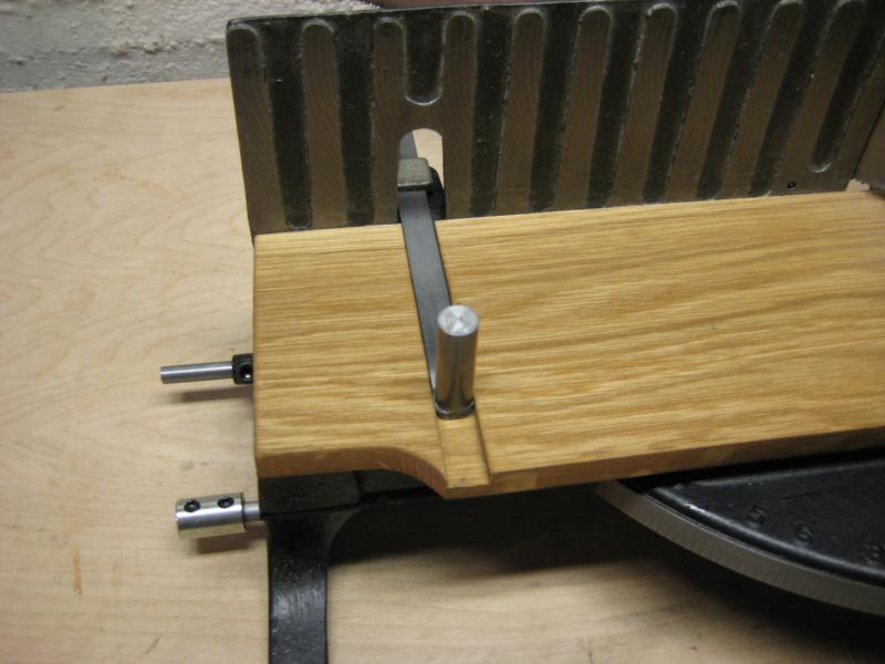
The frame board wasn’t missing but the one it came with was in pretty rough condition. For a replacement I used some 1/4″ thick oak scrap that I trimmed to size using the old one as a template. To make the slots for the stock guides I first sawed edges then chipped out the material in between. I also had to chamfer the back bottom edge of the board so it matched the iron frame. It was finished with two coats of boiled linseed oil.
The crossbar is relatively easy to replace for my version, its just a piece of 1/8″ thick by 1/2″ wide flat steel bar that is long enough to span the gap when the two guide posts are farthest apart. I used the leftovers to make stock guides below. This bar can be seen in the final picture.
Stock Guides
For the stock guides I used some of flat bar left over from the crossbar and some 1/2″ diameter steel rod. I’m not sure on the original dimension of these pieces so I just cut them to lengths that made sense for my mitre box. For the bar, I cut it long enough to go all the way to edge of the frame which was around 8″. I may cut them down a bit in the future because it seems a little too long. The steel rods were cut just tall enough to fit under the opening in the back while on top of the bars. For all the pieces I used a hacksaw and then cleaned up them up with a file.
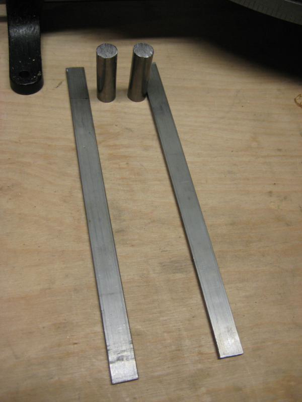 To get the rod ends flat I chucked them up in my drill press and lightly pressed them into a file that was clamped to my drill press table and lubricated with some WD40. I probably committed some machinist sin doing this and it probably wasn’t very good for my drill press, but it worked. Don’t press to hard unless you want to see what gives first when you jam spinning metal into a file. If you have a disc sander or lathe that would probably work better.
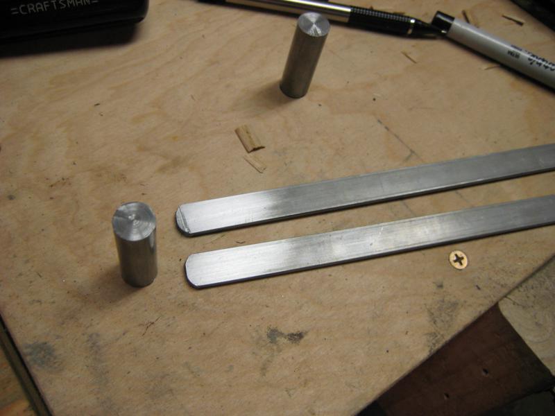 To attach the rod to the bars I used some JB Weld epoxy. Real welding or tapping holes for screws would be a better solution, I don’t have a welder or any taps.
The length stop is used to make repeated length cuts. The parts are broken down below.
Length Stop Rods
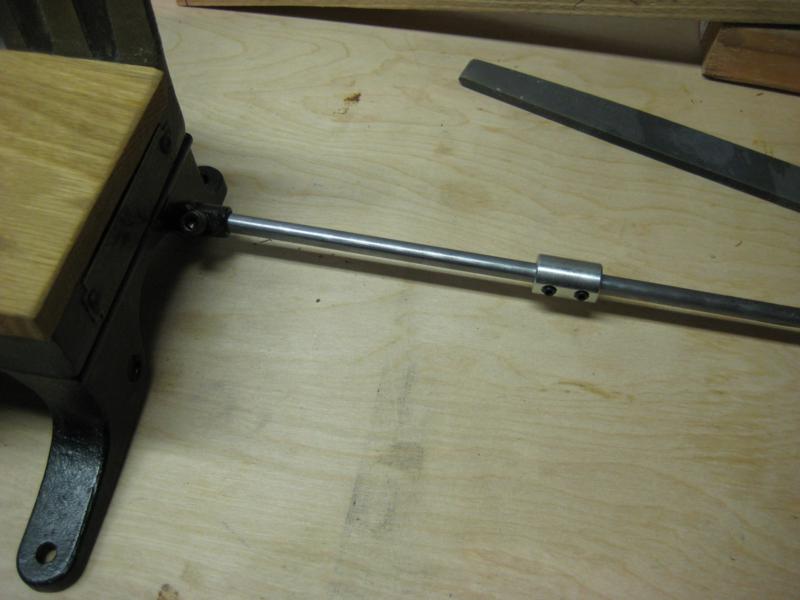
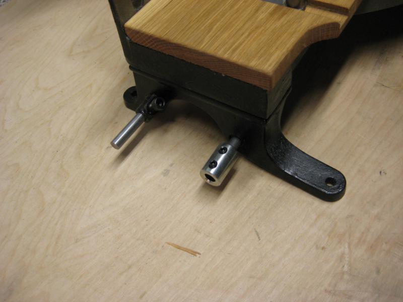
The length stop rods are just 5/16″ steel rods as seen above sticking out of the side. For the 358 I took a 48″ long piece and split it into two. Again see the tooltrip site mentioned above for the recommended length.
Length Stop Rod Coupler
The coupler I found at a fantastic Portland hardware store called WC Winks. Something similar I’m sure can be bought online from McMaster. At some point I’ll probably replace the screws with a filister head screw so I can use a flat head screwdriver for all adjustments.
 ### Length Stop Stand or “Tree”
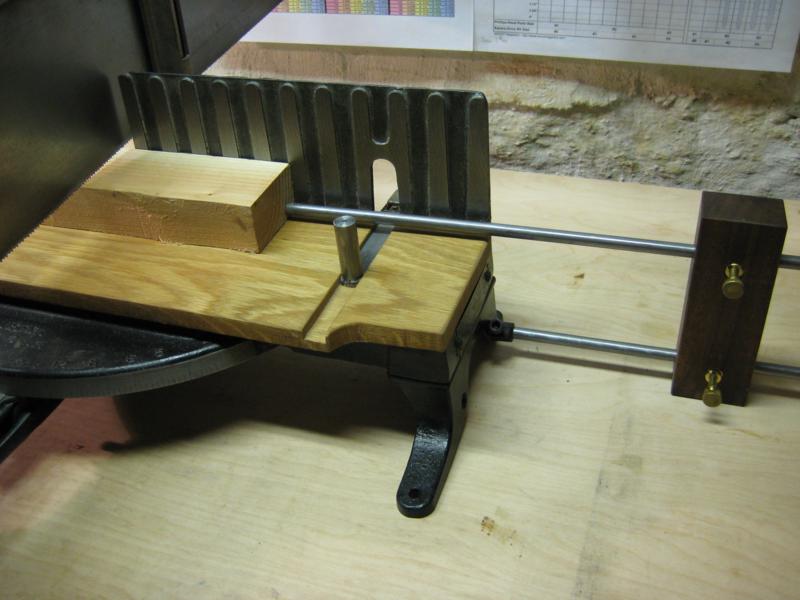
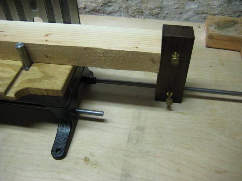
This is probably the hardest piece to find a replacement for. As the tooltrip website says “Get at the back of the line for an original replacement”. For mine I decided to make my own and used a scrap piece of hardwood, some threaded screw inserts and thumb screws.
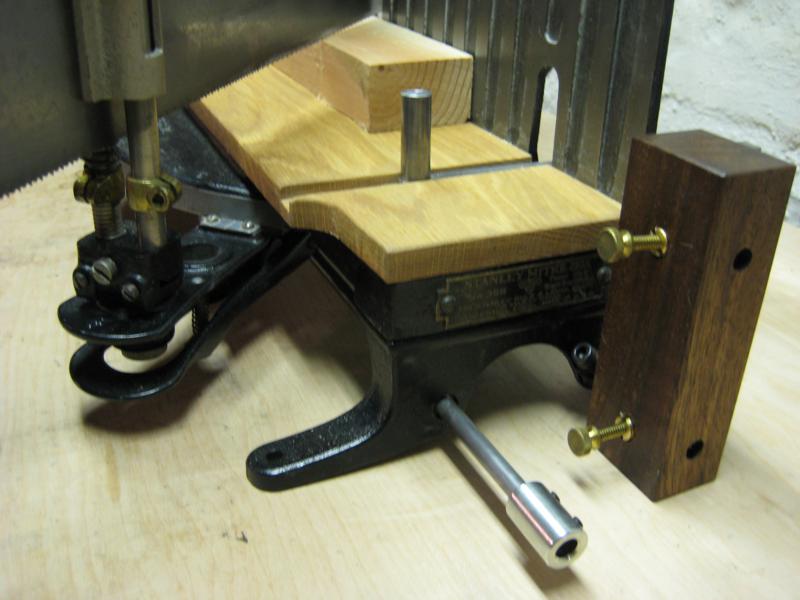 To understand how to make a replacement first understand the three different ways it can be used:
Short Pieces
For pieces that are too short to get to the edge of the frame both rods are used in the stand and the workpiece is butted up against the top rod.
For medium length pieces the workpiece is simply slid over to the length stop stand.
For long pieces the two rods are connected with the rod coupler and the length stop is used in the same manner as above.
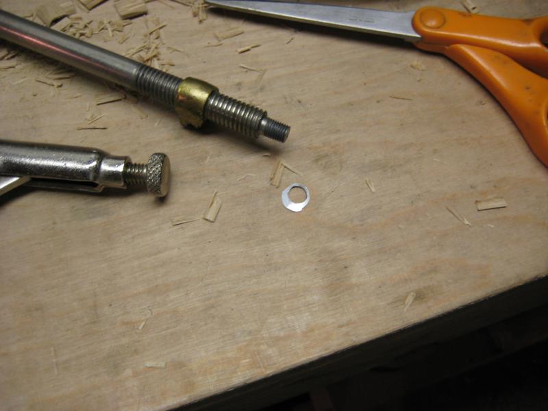
When I re-assembled everything one of the uprights was a little wobbly and I couldn’t tighten it all the way or the top connector pieces wouldn’t line up correctly. To fix this I made a tiny washer out of a pop can using scissors and a hole punch.
And here it is all finished:
